The Technique of Lapping
Conditioning Rings and Functional Principle
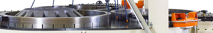
The first feature noticed on a single-plate lapping machine is the rotating working plate, which carries the 3 or 4 conditioning rings. These conditioning rings are guided by roller forks in most cases and rotate with the plate (Figure 16).
How the conditioning rings are driven depends on the friction force in the outer ring circle. This variable is surface, speed, and pressure-dependent; it is in the same direction as the working plate. At the inner diameter of the working plate, the area proportion is significantly lower and the friction force acts in the opposite direction. The difference between these two friction forces, therefore, determines the direction of rotation and the torque, or rotational speed, of the conditioning rings. In practice, the speed of the conditioning rings is approximately the same as that of the working plate. It is important to note that the speed of rotation of the conditioning rings, in addition to their weight, has a considerable influence on the effect the conditioning rings have on the shape of the lapping plate. The heavier the conditioning rings and the larger their surface, the better is the conditioning effect.

Figure 16: Single-plate lapping machine with three conditioning rings
If it is assumed that the lapping plate and the ring rotate at a 1:1 speed ratio, the material removal rate (travel distance) will be identical at each point on the conditioning ring. The process is illustrated by Figures 17, 18 and 19.

The assumption of a 1:1 speed ratio between the working plate and ring is in fact confirmed in practice.
a = Working plate
b = Conditioning ring
Figure 17: Working plate with one ring

The working plate and the conditioning ring
each possess their own peripheral speeds
and specific travel distances. To understand how the conditioning rings keep the working plate flat, it is necessary to grasp that it is the difference in travel distance between the point on the plate and point on the ring (0) that gives the grit particles the opportunity to perform work.
Figure 18: Travel distance difference

The same direction and speed of rotation now results in the following picture: At the outer diameter of the plate, the two
travel distances are covered in the same direction and are subtracted to form the working distance (1). At the inner diameter, by contrast, the two
travel distances are covered in opposing directions, and the travel distance, ring point to plate point, is added to form the
working distance (2). This is clearly shown by the diagram: The working distances are exactly the same at the outer and the inner plate points.
Figure 19: Comparison of travel distances
Assuming a randomly selected point of the specific distances are not only horizontal with respect to the selected point, but also at a certain angle. In other words, at a certain angle with respect to the conditioning ring and working plate.
Nevertheless, the working distance (3) always remains constant, irrespective of the selected point. However, a constant working distance also means that the material removal rate will always be the same at the corresponding radius. The working distance is reduced correspondingly if the radius is smaller. The working distance decreases to the mean working-plate travel distance at the center of the conditioning ring. It is advantageous not to locate workpieces at the center of the conditioning ring. This is possible if templates are used.
According to with studies by Dr. Jochen Kling, formerly of ETH Zurich, Figures 17-19 represent a simplified case. The speed ratio Lambda (conditioning ring working plate) is 1:1 here. At this ratio, the relative speed between the conditioning ring and working plate, or between the workpiece and working plate, is uniform for every point in the ring. This is not the case for other speed ratios; the speed may even become zero. This can necessitate independently driven conditioning rings, but the cost and complexity of the additional mechanism are usually prohibitive.
It is interesting to compare the path described by a point on the ring or on
the workpiece across the working plate. This is a cycloid of a shape depending on the speed ratio and workpiece radius. Figures 20-27 show paths of this kind, with the speed of the conditioning rings being compared with that of the working plate. The ratio Lambda “+” indicates identical directions of rotation, and Lambda “-” indicates opposite directions of rotation with respect to the working plate.

The drawings of Figures 20 to 27 were for a workpiece radius of 0.8 x distance “ring center – ring edge”.

Figure 20:
Lambda = + 0.25
Conditioning ring
rotating at 25% of
plate speed, in
the same direction

Figure 21:
Lambda = + 0.5
Conditioning ring
rotating at 50% of
plate speed, in
the same direction

Figure 22:
Lambda = + l
Conditioning ring
rotating at the
same speed and in
the same direction

Figure 23:
Lambda = + 2
Conditioning ring
rotating at 2x the
plate speed, in
the same direction
Figure 24:
Lambda = – 0.25
Conditioning ring
rotating at 25% of
the plate speed,
in the opposite
direction

Figure 25:
Lambda = – 0.5
Conditioning ring
rotating at 50% of
the plate speed,
in the opposite
direction

Figure 26:
Lambda = – l
Conditioning ring
and plate rotating
at the same speed
and in the
opposite direction

Figure 27:
Lambda = – 2
Conditioning ring
rotating at 2x the
plate speed, in
the opposite
direction
The cycloid paths can be considered as thin strips of material removed from the working plate surface by the particles positioned at the ring or workpiece point. The darker areas in Figures 28 and 29 are a measure of the path density and thus of the material removal at a certain plate radius. It is thus clear how the plate shapes can be influenced by selecting the right speed ratio of the conditioning rings. In simplified form, it can be said that more material removal results in the inner area of the working plate if the conditioning rings rotate in the same direction as the working plate (Figure 29) . If the conditioning rings rotate in the opposite direction, this results in increased material removal in the outer area of the working plate (Figure 28). Figures 28 and 29 show the path of a point on the conditioning ring or workpiece across the working plate.


Figure 28: Lambda approx. – 0.5
(Figure 25)

Figure 29: Lambda approx. + 2
(Figure 23)
The conditioning rings therefore should not rotate with a lambda value greater than 1 (speed equal to the working plate) in order to ensure optimum flatness correction. This is mostly the case in practice, except if the flatness error between the inner diameter and outer diameter is large.
The following flatness errors can result from excessive wear on the working plate by the workpieces:

Concave working surface

Convex working surface

Axial run-out in the working surface
Error la: The concave error in most cases results from too many workpieces in the center of the conditioning ring.
Remedy: Use templates and do not locate parts in the center. Increase intrinsic weight of the conditioning rings.
Error lb: A concave error can also occur if the pressure plate (load plate) is no longer flat.
Remedy: Give the pressure plate a slightly concave shape by lapping it on a slightly convex working plate (use central adjustment facility, also refer to Page 16 “The working plate” and Page 17 “Pressure plates”).
Early detection of an incipient error is important. For this purpose, measuring straight edges with several dial gauges distributed over the entire working plate, are necessary (Figure 31). The errors, and the corresponding correction measures, must be entered in a table (Figure 32). This entry is indispensable, particularly in the Case of shift changes.

Measuring straight
edges

Checklist for
conditioning-ring
adjustment in steps
2.5 mm
Error 2: The convex error can be caused by excessive adjustment of the conditioning rings, which is far less likely. This error can also occur if one conditioning ring is located far out and the others far in on the working plate.
Remedy: Move conditioning rings to center position, load several workpieces in the center of the workpiece holder, load the conditioning rings and lap until the convex error is corrected. Regularly inspect the working plate and check the correction (Figures 31, 32 and 69).
Error 3: The axial run-out error takes a relatively long time to manifest itself. It may be caused by uneven hardness or micro-structure areas in the working plate. However, even an irregularity in the base plate can cause the error. Frequently, the cause is that the base plate and working plate are firmly bolted together, and so-called distortion errors result in the event of temperature fluctuations. Cooled working plates offer a decisive advantage here. With this error, the conditioning rings “ride” as if on a roller-coaster. The same thing naturally also happens with the workpieces. Errors of this type cause long machining times and uneven flatness of the workpieces.
Remedy: If the axial run-out is too large, correction with the conditioning rings will be difficult. The error can be reduced slowly by lowering the support rollers and using a conditioning ring that is at least 33% larger. Workpieces of various sizes should be lapped at the same time. If necessary, a special conditioning plate with a diameter of at least half of the working-plate diameter (it can even extend beyond the center) can be used. Lapping agents should be added to the free area of the working plate. The working plate should be turned on a lathe if the error is too large.
The conditioning ring guide system is provided with a shifting mechanism which, by moving the ring in or out, causes a slight difference in the speed ratio. If the conditioning ring overhangs the inside or outside edge of the working plate, the specific contact pressure increases, and this results in greater material removal.
- Convex working plate: Shift rings towards the center(Figure 69)
- Concave working plate: Shift rings towards the outside (Figure 69)
The conditioning rings and the working plate constitute the most important part of the machine (Figure 16). They fulfill a range of functions:
- Accommodating the workpieces
- Rotating the workpieces during lapping
- Constant conditioning of the working plate during production
- Spreading the lapping medium to a thin film, with uniformly distributed grit particles to ensure perfect seating of the workpiece on the working plate and therefore a perfectly flat surface. The flatness of the lapping plate is copied onto the workpiece.
- Removing the abraded material either into the slots provided in the plate for this purpose, or via the edge of the plate if it is not slotted
- Dissipating heat to the air
- Guiding the workholder, the intermediate layer and the pressure plate (Figure 33)

Schematic drawing of
a lapping process.
You must be logged in to post a comment.