The Technique of Lapping
Measuring
The measurement of thickness and parallelism is relatively easy using
mechanical or electronic measuring instruments. Electronic measuring
instruments with high sensitivity and several measuring ranges down to 0.0001 mm, combined with differential probes, have proven their usefulness in practical applications. They ensure superior precision combined with fast and reliable work.
By contrast, surface finish quality is more difficult to measure. The three
most common methods for specifying a surface roughness value are shown in Figures 46, 47 and 48.
The probes are usually provided with tips of 2 and 5 my radius, and are
applied to the work with very low pressures (e.g. 0.5 to 1 mN). The surface
profile is shown by means of a writing unit or displayed on a screen. Figures 51, 52, 53, 57 and 58 show such recordings.
Flatness measurements are even more complex to obtain than the surface finish quality. However, the interference test instruments now in use (Figure 65 and 66) are precise and simple tools. However, these instruments are suitable only for reflective surfaces.
Newer laser measuring instruments with or without oblique-light measurement (Figure 67) can measure both polished lapped surfaces and matte surfaces. With oblique-light measurement, matte surfaces up to approx. Rt 5 my can be measured. Here, the wavelength A Lambda of 4-6 my is significantly larger than with the vertical method (A 0.6 my). An interference line A/2 shows 2-3 my errors. Light from coarse ground surfaces is diffused due to the larger roughness and is unsuitable for testing.
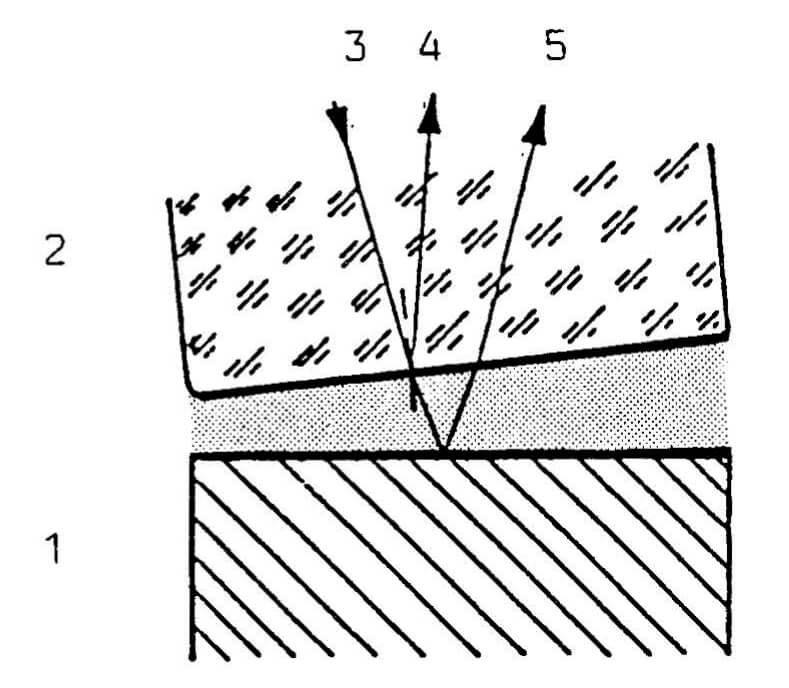
1: Test-piece
2: Optical
3: Incident ray
4: Coherent rays
5: Coherent rays
Figure 64:
Principle of testing with interference unit. Schematic for monochromatic light.
Figure 64 shows the functional principle of these instruments with
monochromatic light. Owing to the various paths taken by the light rays, the eye perceives an interference pattern of light and dark stripes. The pattern of the tested surface can be deduced depending on the shape of these interference lines. This representation can be compared to contour lines on maps (also see Figures 68 + 69).