Flat Honing and Lapping with Two-Wheel Machines
Keeping the Working Wheels Flat
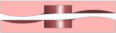
As the removal process of parts occurs, the working wheel performance increases, the wear factors also become more critical. The following faults may occur as the direction of the working wheels change:
Excessive wear on the inside of the lower working wheel causing the upper working wheels to adapt below. Observe the change of direction in the carriers: rotation/counter-rotation.

Excessive wear on the inside of the upper working wheel enables the lower working wheel to adapt above. Observe the change of direction in the carriers: rotation/counter-rotation.
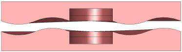
Excessive wear on the inside of the upper and lower working wheels. Wheel design in the inner zone is too weak, so increasing the inner concentration helps improve shape.
Excessive wear on the outside of the upper and lower working wheels. Wheel design in the outer zone is too weak, so to correct this increase the outer concentration.
Excessive wear in the ring of the lower working wheel. This is caused by having too many parts in the center of the carriers with a strong downward wear factor.
Excessive wear in the ring of the upper working wheel. This happens when too many parts are in the center of the carriers with a strong upward wear factor.
Too much frequent change of direction in the carriers due to insufficient parts in the inner ring of the carriers.
Excessive wear load in the ring of the upper and lower working wheels. Meaning there are either too many parts in the inner ring of the carriers or too little exposure.
Undulations in the working wheel due to the uneven arrangement. Uneven hardness causes uneven wear factors on the working surfaces.
Insufficient correction of faults above through the implemented counter-measures due to: -data changes on the machine-made too early -change of work-piece type too early
Figure 26: “Keeping flat” over of faults
So, it is possible to initiate counter-measure in good time by regularly monitoring and frequently measuring the working wheels and the workpieces. There are various possibilities for doing this:
Flatness measurements on the working wheels of two-wheel lapping machines
1. Check procedure
It’s possible to determine the status of the performance of the working wheels with flatness measurements. They can be carried out in two different ways:
a. Using an inspection straightedge, which only shows whether the working wheels are convex or concave.
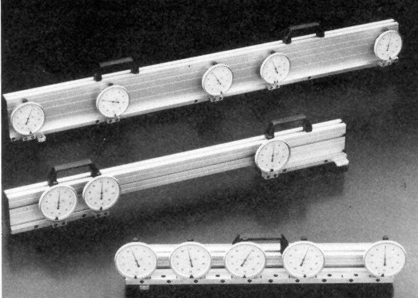
b. Using the precision straightedge with fitted dial gauges (figure 27). This variant displays the precise fault on the working wheel. A minimum of two measurements, each offset by 90 degrees, show the precise status of the working wheel and also possible undulations.
Number of measurements on the working wheels: min. 2 * per day (upper and lower working wheel)
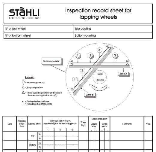
Note: The test paths on the working wheel must be cleaned well. Enter the measured values in an inspection sheet (cf. Figure 28). If in doubt, repeat the procedure.
In the interests of monitoring the results, it is also important to specify the settings of the machine.
- Speeds of the upper working wheel, direction of rotation and time in direction-change cycle 2
- Speed of the lower working wheel, direction of rotation and time in direction-change cycle 2
- Speeds of the inner pin ring, direction of rotation and time in direction-change cycle 2
- Speed of the outer pin ring, direction of rotation and time in direction-change cycle 2
- Working-wheel pressure load in three stages or variably, e.g. 1=100, 2=500, 3=300 daN
In the version with a drive for the outer pin ring and in connection with the speed of the inner and outer pin rings, it is possible to have carriers rotated very quickly or very slowly between the wheels or in their standard position! This option is referred to as the “fourth way” or “fourth axis”. In this case, it is again important to note down the speed, direction of rotation, and time.
During the process, note the work-piece progress on the working wheel. Varying exposure curves can be produces depending on the rotation, counter-rotation, and speeds. Cf. Appendix, Figure 39 Epicycoloids, and hypocycloids.
2. Dressing of the working wheels
The text below provides basic specifications. As a matter of fact, practical experience has shown that the theory often does not match the values on the workpieces measured in practice and the corrections on the machine. Therefore, frequent measurements and logical thinking will help you to harmonize the theory and actual practice better.
Moreover, machining work-pieces with loose or bound grains involves several unknown factors, which may have an influence. The following list simply shows some data which you know and entered into a work card:
- The technical values and faults of the supply to work pieces to be machined, dimensions, position and quantity per work holding plate.
- Designation, number and material of the working plates, hardness, surface consition, full slotted or grooved with specification of the gradient, binding, etc.
- Drawing or production number of the carriers, quantity, material, with and without documentation
- Applied clapping compound and fluid, including volume and mixture ratio
- Pressure and time of the three working cycles and pressure load per cm squared work surface area on the work piece.
- An empty column for comments.
The working wheel performance and ways to improve the process
In most cases, we register a change in performance in the working wheels after positions 1-4, 8 (figure 26). Pos. 8 is due to an excessively high positioning in the center of the carriers. In the event that fewer workpieces are placed in the center of the work holding plate, this causes a more regular cutting speed between the different workpieces and the wear on the working wheel. In practice, it is necessary for the carriers and the tolerable wear. Figures 29-32 show the four versions of the possible variations in the direction of rotation and must be studied in order to avoid more serious flatness faults in good time. Enter all measuring results and procedures in the inspection card!
Explanation of symbols:
e = Outer working zone (external)
i = Inner working zone (internal)
Ve = Outer cutting speed
Vi = Inner cutting speed
Ve1+Vi1 = Speed of the lower working wheel
Ve2+Vi2 = Speed of the upper working wheel
V = Cutting speed
Vw = Speed of workpiece
U +Wear of working wheel
r = Direction of rotation to right (clockwise, viewed from above)
l = Direction of rotation to left (counter-clockwise, view from above)
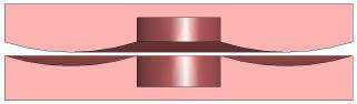
Version 1
The direction of rotation (viewed from above)
- Upper working wheel counter-clockwise
- Carriers clockwise
- Lower working wheel clockwise
The Cutting speed -V- and the resulting wear -U-
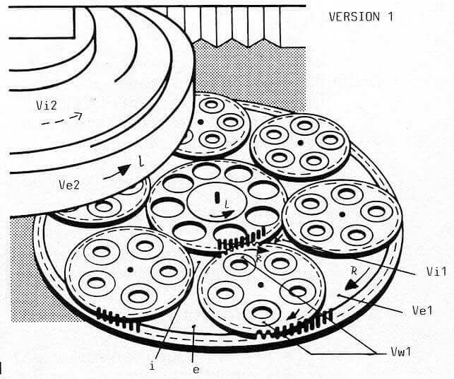
On the upper working wheel
-V-in the zone “e” increases in relation to outer diameter “e” Ve2 + Vw1 -V- in the zone “i” falls in relation to inner diameter “i” Vi2 – Vw1
On the lower working wheel
-V- in the zone “e” falls in relation to the outer diameter
“e” Ve1 – Vw1
-V- in the zone “i” increases in relation to inner diameter “i”Vi1 + Vw1
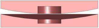
Theoretical conclusion about the deformation of working wheels

Upper working wheel – convex Lower working wheel – concave
Correction recommendation
Reduce the speed of the upper working wheel and increase the speed of the lower wheel, and/or change the direction of the center drive.
Note:
The speed regulation of the working wheels and carriers allows you to influence the wear on the working wheels, and so to improve their flatness. During set-up, pay careful attention to the speed and direction of rotation of the working wheels, the carriers, and the change times.
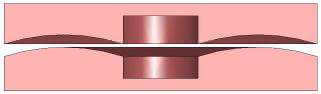
Version 2
The direction of rotation (viewed from above)

- Upper working wheel clockwise
- Carriers counter-clockwise
- Lower working wheel counter-clockwise
The cutting speed -V- and the resulting wear -U-
On the upper working wheel
-V- in the zone “e” increases in relation to outer diameter “e” Ve2+Vw1
-V- in the zone “i” falls in relation to inner diameter “i” Vi1 + Vw1
Theoretical conclusion about the deformation of working wheels

Upper working wheel – convex
Lower working wheel – Concave
Correction recommendation
Given these points, reduce the speed of the upper working wheel and increases the speed of the lower, and/or change the direction of rotation of the center drive.
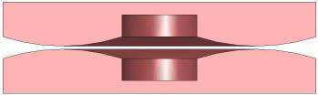
Version 3
The direction of rotation (viewed from above)
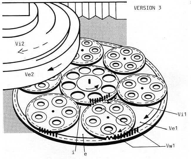
- Upper working wheel clockwise
- Carriers clockwise
- Lower working wheel clockwise
Figure 31: Wheel behavior, version 3
The cutting speed -V- and the resulting wear -U-
On the upper working wheel
-V- in the zone “e” falls in relation to outer diameter “e” Ve2 – Vw1
-V- in the zone “i” increases in relation to inner diameter “i” Vi2+Vw1
On the lower working wheel
-V- in the zone “e” falls in relation to outer diameter “e” Ve1 – Vw1
-V- in the zone “i” increases in relation to inner diameter “i” Vi1 + Vw1
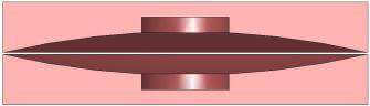
Theoretical conclusion about the deformation of working wheels

Upper working wheel – concave Lower working wheel – concave
Correction recommendation for improving the performance of working wheels
Reduce the speed of the carriers and/or change the direction of rotation of the center drive.
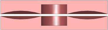
Version 4
The direction of rotation (viewed from above)
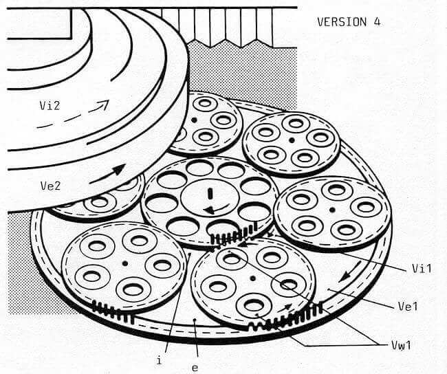
- Upper working wheel counter clockwise
- Carriers counter-clockwise
- Lower working wheel clockwise
Figure 32: Wheel behavior, version 4
The cutting speed -V- and the zone “e” falls in relation to outer diameter “e” Ve2-Vw1
-V- in the zone “i” increases in relation to inner diameter “i” Vi2 + Vw1
On the upper working wheel
-V- in the zone “e” falls in relation to outer diameter “e” Ve2 – Vw1
-V- in the zone “i” increases in relation to inner diameter “i” Vi2 + Vw1
On the lower working wheel
-V- in the zone “e” increases in relation to outer diameter “e” Ve1 + Vw1
-V- in the zone “i” falls in relation to inner diameter “i” Vi-Vw1
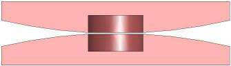
Theoretical conclusion about the deformation of working wheels
Upper working wheel – concave Lower working wheel – Convex
Correction recommendation to improve the performance of working wheels
Ultimately, reducing the speed of the carriers and/or change the direction of rotation of the center drive for correction.
Other possibilities for correcting the working wheels:
- Dressing the working wheels during lapping is carried out using slotted dressing rings made of special gray cast iron that are driven by toothed gears.
- Dressing the working wheels during flathoning is carried out using abrasive products inserted in the cages.
- Flat lathing or grinding is another solution, but will probably be the most expensive.
Dressing, either periodically or at the end of a working day, reduces the running times, and with optimal use, increases the service life of the working wheels. It is particularly necessary to use this procedure when the workpieces to be machined need to possess an extremely precise flatness tolerance.
As a result, the quality of the flatness and the parallelism of the workpieces will remain constant if the machine is well maintained and checked regularly by the user and the speeds and directions of the rotation of the carriers and the working wheels are varied. In order to achieve this result, the user must carry out the technical measurements regularly and methodically. (cf. Figures 27, 28). The applied corrections on the machine must be tried out first before any further corrections are made. It is always advisable to consider what may be causing the fault, and then to take the necessary countermeasures in good time. The corrections must be entered regularly in the inspection card.
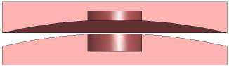
Progress of a round wheel on faulty working wheels
(dr. Kling, ETH Zurich 1990)
Figure 33 shows the cutting fields that the workpieces must pass through on faulty working wheels. It would be interesting to be able to determine the splitting pressure. Consequently, this may range between an extremely high-pressure load and lying entirely free. Thus, the lapping or liquid film will be extremely uneven, and it may even break. It is quite clear that the shortest machining time and the best quality are produced if both working wheels possess the perfect flatness.